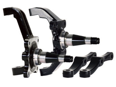
My front suspension is a tubular double A-Arm and uses a Wilwood ProSpindle based on Mustang II front ends, The Mustang II is a common aftermarket front end used on a variety of hot rods. This makes the componets easy to acquire and relatively inexpensive. The Wilwood spindle was my starting point for the A-Arm design as I wanted “off the shelf” components where possible. While not a true Mustang II spindle geometry, it does accept standard wheel hubs and bearings and the updgraded Wilwood brakes that I intend to use.
The front wheel track of the RT is much wider in stance than the Mustang II so using standard A-Arms would not provide the correct geometry for the suspension travel. I made this an educational section of the build so I bought some books, did tons of research and learned much about suspensions. One thing I learned right away is that suspension design is a compromise and there is no single “correct” design geometry. The balance between toe, camber and castor is based on the type of ride experience desired and constantly changes as the car accelerates, steers and bounces. Keeping the feel and experience the same throughout suspension travel is the key parameter.
Keeping this in mind I chose to purchase a suspension design software that I could use to “tune” my design to the experience I was looking for and to match the geometry of the RT. The software is called “Suspension Analyzer” from Performance Trends . I know this will be a learning experience and expect to make changes as the RT is driven and I take data on the handling parameters, but I want to start with a goal in mind and design the components as close to that goal as possible from the start.
The software starts with the basic three dimensional coordinates of the moving suspension parts; upper a-arms, lower a-arms, tie rods, shocks, springs, etc. Tire and wheel parameters are selected as well and all components can be tweaked to see the desired results as you “move” the suspension through its range of motion. All pretty cool to an engineering guy like me who wants to know how things work and how changes will alter behavior of the suspension.
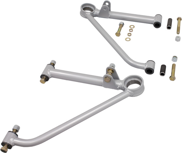
After getting some basic geometry by reverse engineering some info on the T-Rex, I started to lay out the design and test the geometry. I settled on a good compromise that met my design goals. I was fortunate early on in my research to find a lower a-arm from Chris Alston’s Chassisworks that was nearly identical to the dimensions I desired. I really didn’t want to fabricate the a-arms from scratch and this was a nearly perfect fit. I altered my design to fit this lower a-arm and along with the Wilwood spindle I only had to fabricate the upper a-arms. As I began my search for how I was going to build the upper a-arms I stumbled upon Victory Circle Chassis and Parts who had 2011 IMCA approved modified a-arms that were also very close to what I needed geometry-wise so I ordered a couple and it was almost too good to be true – they fit perfectly! I designed the a-arm to use Heim style joints allowing easy adjustment in all three dimensions to fine tune the suspension.
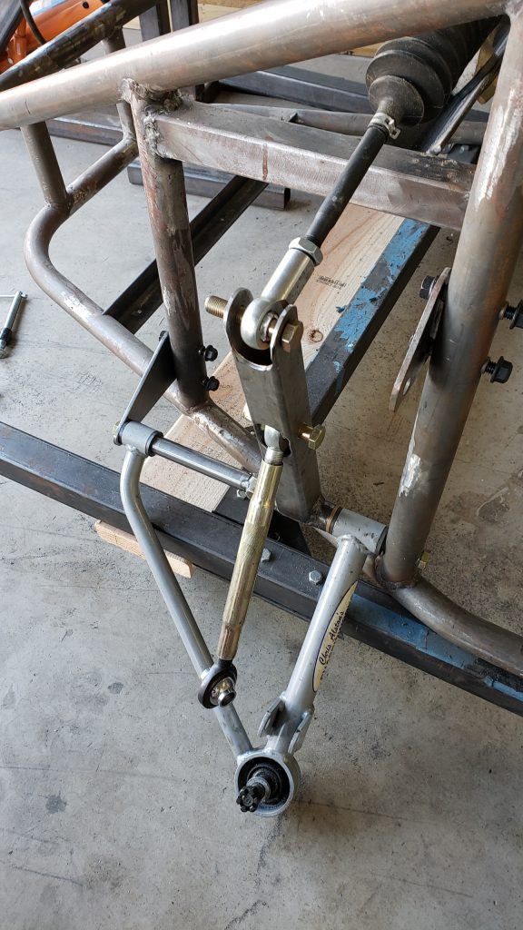
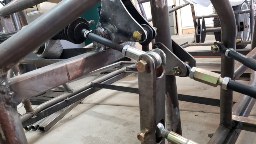
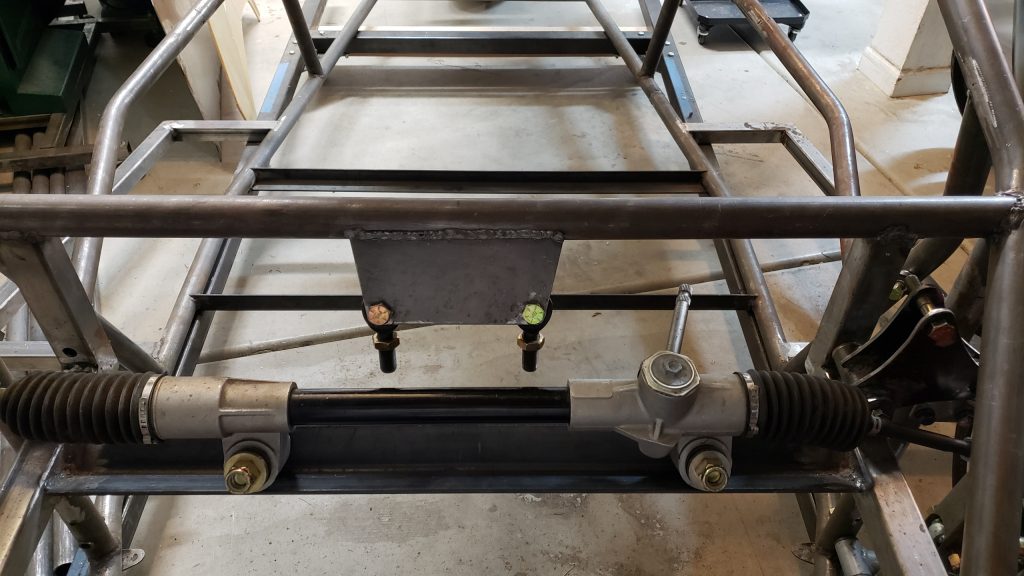
The steering geometry is such that the off-the-shelf rack and pinion will not give the best handling if it is attached as-is to the steering arm on the spindles. Instead of customizing the rack and pinion I made a intermediate arm that pivots off the lower a-arm pivot shaft. I used a small lathe to make the shaft which is drilled and tapped at each end to accept the 1/2-inch diameter a-arm attach bolts. The shaft is 3/4-inch diameter reduced to 5/8-inch about half way across. The 5/8-inch side of the shaft is used as the pivot for the intermediate arm. The arm attaches at the top to the rack and pinion tie rod arm by way of a 9/16-inch female threaded heim joint with 1/2-inch bolt hole. The steering arm is attached a few inches below this point because this gave the best steering geometry relative to the rest of the a-arm geometry. As the rack and pinion tie rod moves in and out, the intermediate arm pivots and allows the steering arm to move in and out as well. Because the arms are attached at the intermediate arm at different lengths along the intermediate arm from the pivot point, there is a change in travel distance of the steering arm relative to the tie rod arm. This has the affect of giving the rack a smaller steering ratio. In other words, it will take more turns of the steering wheel to get the same turn angle of the wheels. If this turns out to be an issue I can exchange the rack and pinion for a quick turn rack and get a typical turn ratio back. Below is a picture showing the lower a-arm and pivot shaft, intermediate arm, and steering arm temporarily attached to the rack and pinion tie rod arm.
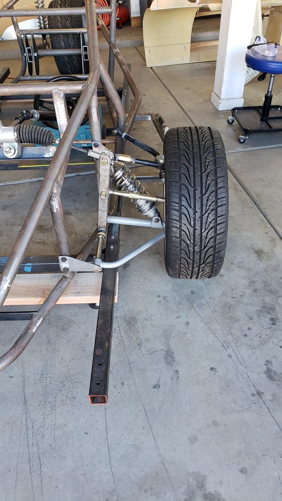
Here is another view with the upper a-arm attached and the wheel mounted including the front shock. I’m still debating if I want to move the shock inside the chassis and convert the front suspension to a cantilever style. This would remove the weight of the shock and coil spring from the suspension and provide additional suspension benefits.
After doing some layout options in SolidWorks, I decided to switch to the cantilever suspension style. This involved fabricating a push-pull pulley for the left and right side of the suspension and mount it to the rack and pinion supports I installed previously. It was a perfect location for the pulleys and made mounting them almost too simple.
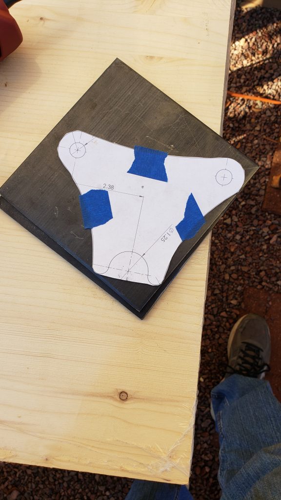
The pulley are fabricated from 3/16″ thick steel plate so I started by cutting a template to guide the steel cuts. The pulley plates are welded to a short steel tube and 5/8″ ID bronze bushings are installed in the tube to act as pivot bushings. The plates have 1/2″ holes drilled to accept 5/8″ heim joints with 1/2″ bores/bolts. One joint is attached to the shock and the other is attached to a shaft running to the lower a-arm (where the shock on a traditional suspension would attach).
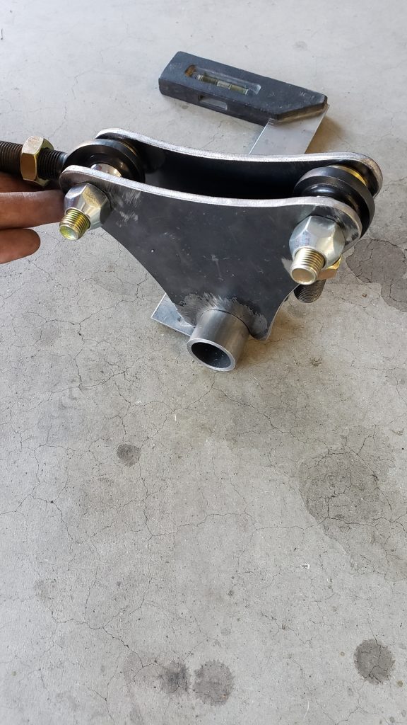
The pulley was attached to a 1-1/2″ square tube I had previously installed in the chassis to support the rack and pinion as well as to support the back of the instrument panel. This turned out to be a perfect location for the pullies to mount to. I welded a tab to support one end of the 5/8″ pulley bolt and drilled a hole in the vertical square tube (instrument panel support) to support the other end.
Now that the pulley is installed to translate the a-arm vertical movement into a horizontal movement, I needed to fabricate a support mount for the shock so that it lays in a horizontal direction. The middle brace of the A-pillar, which is essentially in line with the lower edge of the front window, is where I elected to weld the support. Its just a pair of 3/16″ plate with 1/2″ bolt holes drilled in it to support the bottom end of the shock. They are at a slight angle relative to the A-pillar angle to get the shocks aligned well with the cantilever pulley.
Mounting the shocks and assembling the cantilever arms and heim joints now completed the cantilever shock assembly.
I wanted to test the suspension as soon as possible, so I turned my attention to greasing the rotor bearings, installing the rotors to the spindles and attaching the brake calipers. I will route the brake lines later when I get closer to final assembly. I then mounted the two front wheels for the first time. I could now lower the chassis off of its assembly frame and put its full weight on the front suspension. I needed to do some slight adjustments to the shocks and cantilever arms once there was weight on it, but it held the weight perfectly. I took the opportunity to jump up and down on the front of the chassis to watch the suspension in action and it all worked perfectly!